
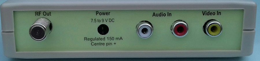
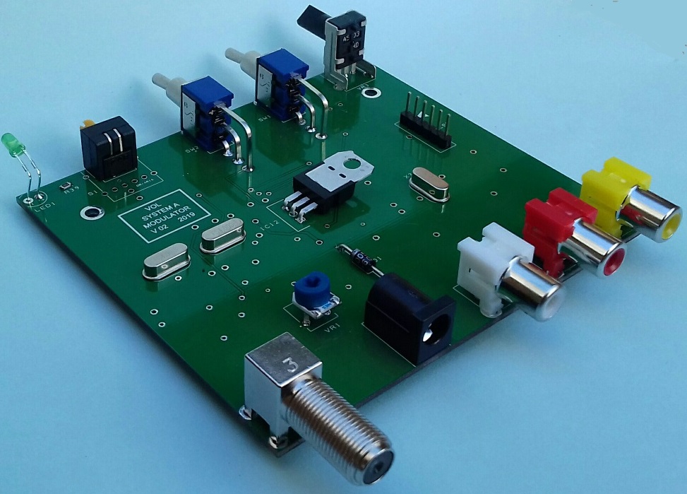
Vol is a homebrew System A Modulator which uses two MC44BS373CA modulator chips and a PIC18F24K22 microcontroller. On this page you will find the files required to build it.
All material including Downloads on these pages are provided 'as is' without warranty of any kind, either expressed or implied.
This is my version of a system A modulator design by David Robinson which I first seen in
this
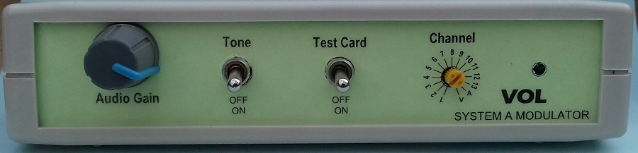
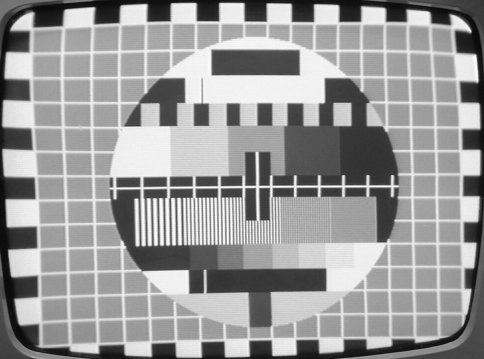
thread on UK Vintage Radio Repair and Restoration Forum. The video and audio modulators are practically identical. The main difference is the addition of a test card and audio tone.
This is my second version a link to a thread detailing my first version can be found
here
. The difference between the first and second versions is an improved test card and switches to select the test card and test tone. Also the audio gain control has been moved to the front panel.
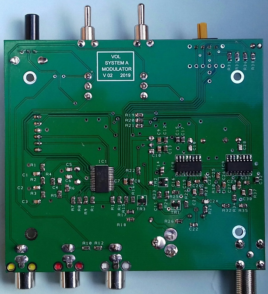
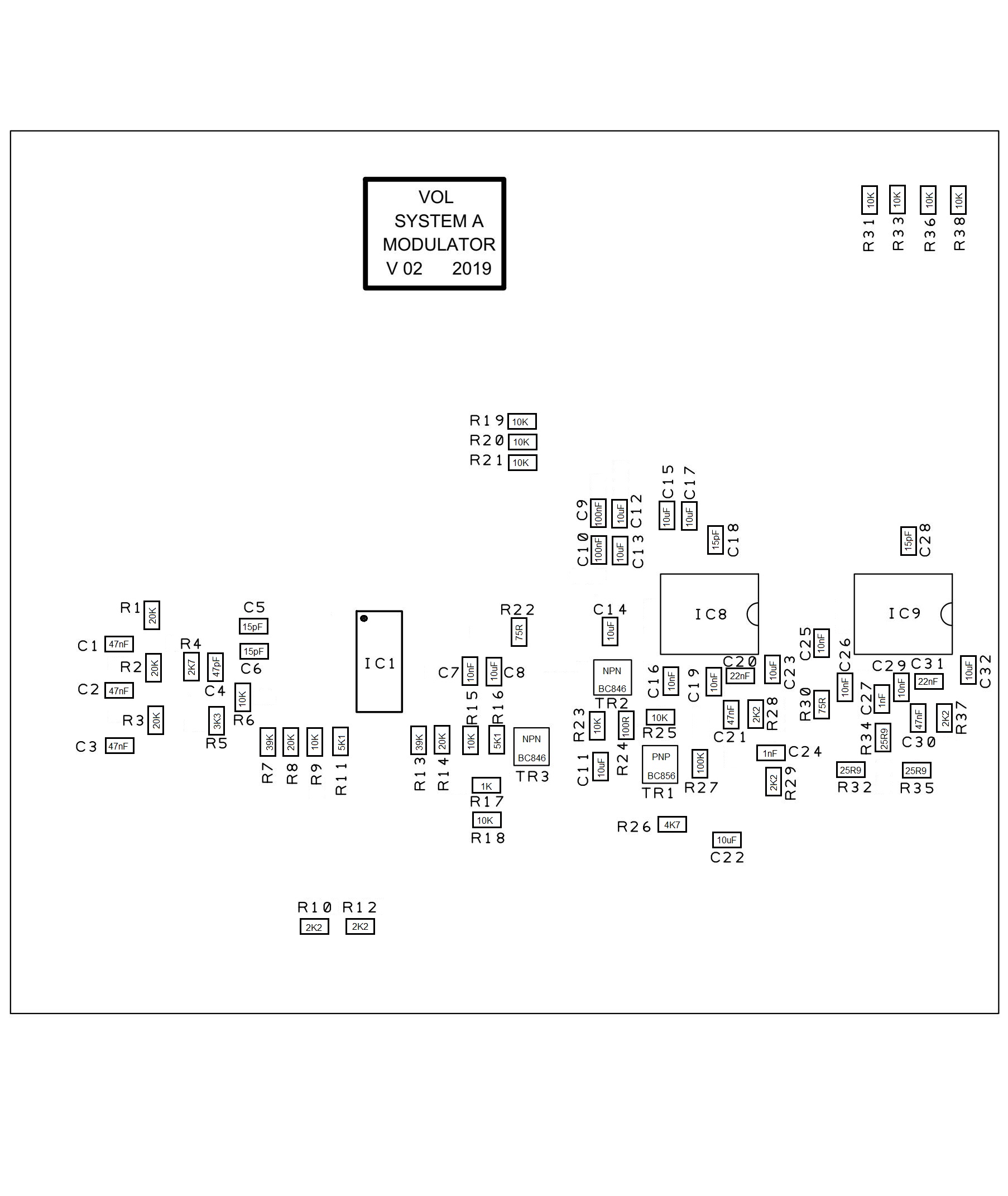
All Resistors, Capacitors and Inductors are 0805 size.
All Capacitors are ceramic multilayer types.
Where given manufacturers part numbers are given as examples alternative parts may also suit.
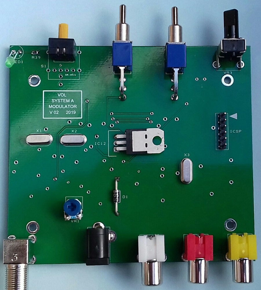
The PCB is double sided and measures 100 mm X 89.5 mm.
Link to uploaded Gerber files on PCBWay
The modulator has a built in 4:3 test card loosely based on the Phillips PM5544. It has frequency gratings of 1, 1.5, 1.88, 2.5 and 3 MHz.
The channels are selected by a Hex switch. Positions 1 to 13 are the channels. The positions marked "V" and "A" are both channel 1 can be used to set up the audio carrier.
"V" = video modulator only.
"A" = audio modulator only.
Circuit diagram (.pdf)
Component list (.pdf)
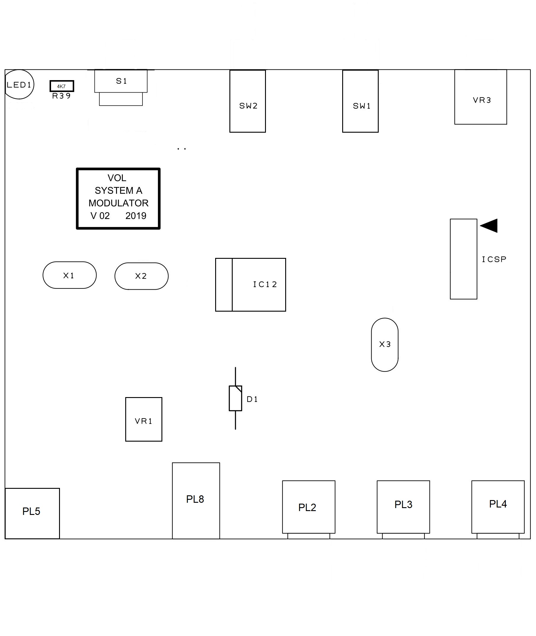
Component layout top (.jpg)
Component layout bottom (.jpg)
Front and rear panel legends (.pdf)
Microcontroller program file (.hex)